A Short Guide To Metric Nuts and Bolts
A Short Guide To Metric Nuts and Bolts
Answers to the most Frequently Asked Questions
- Standard and Fine Pitch Threads
- How to identify nut and bolt strength grades
- How nut and bolt strength grades compare
- Maximum Tightening Torques
- Why specified torque is sometimes lower than the maximum
- Spanner Sizes Versus Bolt / Nut thread size
- Allen Key size versus Bolt / Nut thread size
- Correct Drill size for Tapping Metric threads in holes
Introduction: Metric Nuts and Bolts
This short guide is intended to give a very basic introduction to ISO metric nuts and bolts. It is intended for those working in plant and machinery maintenance to give enough information on to ensure that correct replacement parts are identified and used.
Few parts are as critical in the assembly of modern machinery as the nuts and bolts which hold it all together and, at first sight, it seems that all metric bolts are basically the same.
In fact, of course, nothing could be further from the truth. There are no fewer than 5 different threads for different applications and 10 different standard strength grades defined for each size of bolt. There are nineteen standard sizes – known as the ‘preferred ‘ sizes and ten less commonly used (the so-called ‘non-preferred’) sizes.
The situation on is almost as complex with metric nuts which come in a wide variety of types (full, thin, nyloc, castellated…..) and 5 strength grades as well as the same range of sizes.
The difference in strength between different grades is quite dramatic: the highest standard grade being capable of carrying more than three times as much load as the lowest grade.
If you are responsible for repairing and maintaining machinery, particularly if that machinery is involved in lifting operation or other safety critical applications then you will be aware of the importance of fitting the right parts in the right way. This short guide is intended to give you the information you need to be able to correctly identify and use the metric nuts and bolts most commonly found in plant and machinery.
Disclaimer
Every effort has been made to ensure that the information
contained in this document is correct but no guarantee can be
given nor liability accepted for errors or omissions
We are always grateful for any comments or criticisms of our technical
publications and are happy to off er advice on all aspects of plant and machiery maintenance.
Should you have any feedback concerning this document please contact us:
Thomson Engineering Design Ltd, Units 2a & 3 Crabtree Road, Cinderford,
Gloucestershire GL14 2YN
Tel: 01594 82 66 11 or Email: technical@thomsondesignuk.com
Standard and Fine Pitch Threads
Although various special threads are defined by the ISO standard only two are in common use in most machinery, the others are mainly used in specialist equipment such as precision instruments, optical instruments, etc.
The two threads most commonly found in plant and machinery are usually
known as ‘standard’ and ‘fine’ pitch.
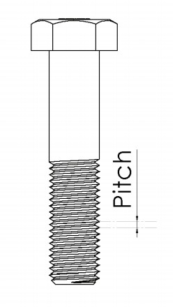
The pitch of a thread is the distance between two adjacent threads and is
measured in millimetres.
The most common thread diameter and pitch combinations found in plant and machinery are listed in the table below:
| Size | Pitch (std) | Pitch (fine) |
|---|---|---|
| M5 | 0.8 | 0.5 |
| M6 | 1.0 | 0.75 |
| M8 | 1.25 | 1.0 |
| M10 | 1.5 | 1.0 or 1.25 |
| M12 | 1.75 | 1.5 |
| M16 | 2.0 | 1.5 |
| M20 | 2.5 | 1.5 |
| M24 | 3.0 | 2.0 |
| M30 | 3.5 | 2.0 |
How to Identify the Strength Grade of Nuts and Bolts
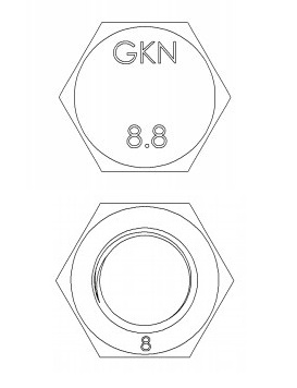
Except for the very lowest grades, metric nuts and bolts all carry identification markings which indicate their strength.
On the head of each bolt are two numbers separated by a decimal point, the full list includes ten grades from 3.6 to 14.9 but in plant and machinery only grades 8.8, 9.8, 10.9 and 12.9 are normally found. The bolt head should also have a code – normally two or three letters – indicating the manufacturer.
Usually the markings are on the top of the bolt head but sometimes they are on the side.
The first number gives the breaking strength of the steel in the bolt. In round terms it is in 10’s of kg per square millimeter of the bolt cross second.
For example, a grade 12.9 bolt will not snap until every square millimetre of the bolt cross section is carrying a load of at least 120 kg. Similarly a grade 8.8 bolt will not snap until it is carrying a load of 80kg per square millimetre.
If a bolt is progressively loaded it extends very slightly – like a spring does and it springs back to its original length if the load is released. However, there is a limiting load where the bolt no longer springs back all the way and instead remains permanently stretched, this is know as the yield point. The second number on the head of the bolt indicates how much of the breaking strength the bolt can stand before it starts to stretch.
For example, a grade 12.9 bolt will begin to stretch when the load on the bolt is 90% of the breaking load. Similarly a grade 9.8 bolt will begin to stretch at 80% of its breaking load.
The strength grade marking is more difficult to see on metric nuts, sometimes it is given as a number, sometimes as a pattern of a dot and a line where the position of the line indicates the grade like the hands of a clock.
Where the grade is given as a number it may be stamped on the top of the nut or on one of the flat sides.
Clock face grade marks are shown in the illustration (right). Put the dot at the twelve O-Clock positions and the line shows the grade.
‘Clock Face’ Grade Marking

The rule is that the grade of the nut should always be the same as the bolt grade or one grade higher so: a grade 8.8 bolt should be fitted with a grade 8 or grade 9 nut. A grade 12.9 bolt should be fitted with a grade 12 or grade 14 nut.
How the Different Strength Grades Compare
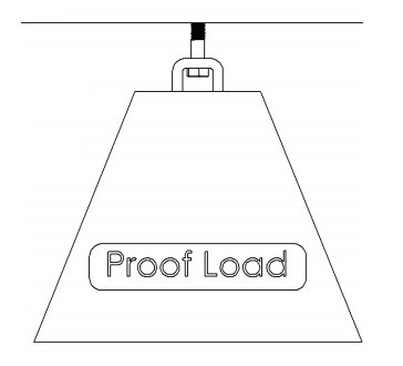
As we said on page 4, if a bolt is gradually loaded there comes a point when it begins to yield (to permanently stretch) and if the load contiues to increase, a point where it actually breaks. When deciding how much load can safely carry, the standards define a ‘proof load’ – typically 90% of the load required to stretch the bolt.
Proof loads are normally given in Newtons in manufacturers tables but here we’ve converted them into kg force. The proof load is usually considered to be the absolute maximum load which a bolt should be asked to carry.
In practice, manufacturers will design their machinery so that the bolts carry a lot less than the proof load to give a good safety factor to the design.
Proof Loads for Standard Pitch Bolts
| Size | Grade 8.8 | Grade 9.8 | Grade 10.9 | Grade 12.9 |
|---|---|---|---|---|
| M5 | 820 kg | 923kg | 1,180kg | 1,380kg |
| M6 | 1,160kg | 1,310kg | 1,670kg | 1,950kg |
| M8 | 2,120kg | 2,380kg | 3,040kg | 3,550kg |
| M10 | 3,370kg | 3,770kg | 4,810kg | 5,630kg |
| M12 | 4,890kg | 5,480kg | 7,000kg | 8,180kg |
| M16 | 9,100kg | 10,200kg | 13,000kg | 15,200kg |
| M20 | 14,700kg | N/A | 20,300kg | 23,800kg |
| M24 | 21,200kg | N/A | 29,300kg | 34,200kg |
| M30 | 33,700kg | N/A | 46,600kg | 54,400kg |
Fine pitch bolts will be typically 10% stronger than coarse pitch bolts because
less metal is cut away to make the thread.
Maximum Tightening Torques
The maximum recommended torques given in the table below assume that the threads are lightly oiled. Doing a bolt up to the specified torque should set the tension in the bolt to approximately 85% of the proof load given in the table on page 5 which equates to 62% of the breaking load.
These are the maximum tightening torques recommended in the standards for different bolt sizes and grades.
ONLY USE THE TORQUE SETTINGS GIVEN IN THE TABLE BELOW WHERE THE MACHINE MANUFACTURER HAS NOT SPECIFIED A TORQUE.
For Standard Pitch Bolts and Nuts
| Size | Grade 8.8 | Grade 9.8 | Grade 10.9 | Grade 12.9 |
|---|---|---|---|---|
| M5 | 7.0 Nm | 7.8 Nm | 10.0 Nm | 11.7 Nm |
| M6 | 11.8 Nm | 13.3 Nm | 17.0 Nm | 19.9 Nm |
| M8 | 28.8 Nm | 32.3 Nm | 41.3 Nm | 48.3 Nm |
| M10 | 57.3 Nm | 64.1 Nm | 81.8 Nm | 95.7 Nm |
| M12 | 99.8 Nm | 111.8 Nm | 142.8 Nm | 166.9 Nm |
| M16 | 247.5 Nm | 277.4 Nm | 353.6 Nm | 413.4 Nm |
| M20 | 499.8 Nm | N/A | 690.2 Nm | 809.2 Nm |
| M24 | 865.0 Nm | N/A | 1,195.4 Nm | 1,395.3 Nm |
| M30 | 1,718.7 Nm | N/A | 2,376.6 Nm | 2,774.4 Nm |
Fine pitch nuts and bolts are normally only used in special circumstances and
the manufacturer’s maintenance documentation should give the required
torque in each case.
Fine threads are often used where a bolt is screwed into a soft metal block,
such as an aluminium casting, the thread in the block may be far weaker than
the bolt and a lower torque is almost always required to avoid stripping the
threads.
Why Manufacturers Sometimes Specify a Lower Torque
Many factors affect the strength of threads in components including how the thread is produced, the surface finish and the accuracy of the thread shape.
The strength of the threaded connection is the strength of the weakest part so, for example, if a high tensile bolt is screwed into a softer, more ductile material such as an aluminium alloy or low carbon steel part then it will be the softer part which dictates the maximum torque which can safely be applied to the bolt.
More often though a bolt has to carry not just the tension load due to its tightness but also a sideways or ‘shear’ load. A typical example of this is shown in the illustrations where two plates are bolted together then subjected to a load which places a shear load on the bolt.
Friction between the plates caused by the tightness of the bolt might be enough to stop the plates actually moving if the applied load is quite small but normally, unless dowel pegs are fitted to carry the shear loads, the bolts end up carrying the shear stress as well as the tension stress. Adding these two stresses together creates a total stress which is bigger than either the shear or the tension stresses – so the pre torque of the bolt may be less than the maximum given on page 6 to allow it to cope with the extra stress due to shear.
The calculations for this scenario can be quite complex but, for guidance, reducing the tightening torque of the bolt by 10% allows up to 35% of the bolt’s load rating to be carried in the shear direction without overloading the bolt.
Design Engineers have to consider all these factors and may decide that a lower torque is applicable. This is commonly the case in lifting devices where high factors of safety are required.
Always refer to the machine manufacturers’ maintenance documentation for the specified torque of bolts and nuts used in lifting and load bearing applications.
Spanner and Allen Key Sizes
Correct Spanner and Allen Key sizes are given in the table below for the normal range of bolt and nut sizes found in plant and machinery.
To minimise the risk of a spanner slipping and marring the corners of a fastener, it is good practise to use ring spanners (or the ring end of a combination spanner) whenever possible.
| Size | Spanner | Allen Key |
|---|---|---|
| M5 | 8 mm | 4 mm |
| M6 | 10 mm | 5 mm |
| M8 | 13 mm | 6 mm |
| M10 | 17 mm | 8 mm |
| M12 | 19 mm | 10 mm |
| M16 | 24 mm | 14 mm |
| M20 | 30 mm | 17 mm |
| M24 | 36 mm | 19 mm |
| M30 | 46 mm |
Tapping Drill and Clearance Hole Drill Sizes
Metric bolts are made fractionally under their stated size, for instance an M16 bolt will have a shank diameter of typically 15.97mm. This means that a 16mm bolt will fit through a 16mm hole but to allow for misalignment between parts it is common practice to drill bolt holes slightly larger. These are known as clearance holes.
Typical clearance hole sizes are given in the table below along with the correct tapping hole size for each size of standard and fine pitch thread.
With metric threads tapping drill size is easy to work out because it is the bolt diameter minus the thread pitch so, for example, a standard pitch M16 bolt has a pitch of 2.0mm so the tapping drill size is 16 – 2 = 14mm.
The table below gives tapping drill sizes for threads corresponding to the thread pitches given in the table on page 3.
| Size | Clearance Hole | Thread Pitch (std) | Tapping Drill (std Pitch) | Thread Pitch (fine) | Tapping Drill (fine pitch) |
|---|---|---|---|---|---|
| M5 | 5.5 | 0.8 | 4.2 mm | 0.5 | 4.5mm |
| M6 | 6.5 | 1.0 | 5.0 mm | 0.75 | 5.25 mm |
| M8 | 9 | 1.25 | 6.75 mm | 1.0 | 7 mm |
| M10 | 11 | 1.5 | 8.5 mm | 1.0 or 1.25 | 9.0 or 8.75 mm |
| M12 | 14 | 1.75 | 10.25 mm | 1.5 | 10.5 mm |
| M16 | 18 | 2.0 | 14 mm | 1.5 | 16.5 mm |
| M20 | 22 | 2.5 | 17.5 mm | 1.5 | 20.5 mm |
| M24 | 26 | 3.0 | 21 mm | 2.0 | 22 mm |
| M30 | 32 | 3.5 | 26.5 mm | 2.0 | 28 mm |
When tapping a hole, particularly M10 and smaller, remember to keep removing the tap from the hole and blowing away the swarf to prevent the tap jamming and breaking.
Converting Torque to Tensile Load in a Bolted Fastening
When a bolt is tightened into a thread or a nut and bolt are tightened to squeeze two parts together, the torque applied to the assembly sets up a tension load in the shank of the bolt.
The actual force in the bolt depends on a lot of factors including the shape of the thread, the thread pitch, the thread surface finish and the amount and type of lubricant on the thread.
Happily for most normal circumstances when using metric bolts with the standard ‘coarse‘ thread pitch and with threads lightly lubricated, the force in the bolt can be easily calculated as:
Force = 5 x Torque / Diameter
Where the force is in Newton, Torque is in Newton metres and Diameter is in metres – watch out for this otherwise your results will be 1000 times wrong.
As a worked example for an M16 bolt tightened to 247.5Nm the force is:
Force = 5 x 247.5Nm/0.016m = 77344N or 77.3 kN
Note that the 16mm bolt diameter is converted to 0.016m in the calculation.
To convert the force in Newton to a kg force we divide by 9.81 (or by 10 if we’re in a hurry) to give a bolt load of 7,884kgf.
If the threads are dry the increased friction in the thread will result in a lower
force.
Common Types of Failure in Bolted Joints
There are three main ways in which a bolted connection can fail: by shearing of the bolt, by tensile fracture of the bolt and by failure of the threads.
Tensile failure of the bolts, where the bolt simply snaps, is caused by overloading of the joint or by overtightening the bolts on installation. The bolt most usually fails where the thread meets the shank.
Shear failure where the bolt is ‘scissored’ off is, again, most usually due to overloading of the joint but it can be because the bolts were overtightened using all the bolts’ strength to carry the tension in the bolt with none left for the shear load. Both tensile and shear failures commonly occur early on in the life of the assembly or near end-of-life.
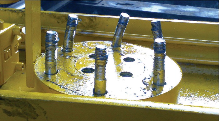
The picture below shows the most common type of failure in service. Here a bolted flange joint designed for a simple tensile load was accidentally subjected to a sideways load as well which levered the nuts off the bolts starting with the ones in the foreground. This led to a cascade failure of the remaining bolts with the last two at the back of the image also bending as they were torn apart.
In this type of failure the taper of the threads causes the nuts to swell, stretching outwards, leaving less of the nut thread engaged with the bolt thread and eventually the metal of either the bolt or the nut thread gives way and the thread is stripped off the bolt or out of the nut. Nyloc nuts were used in this assembly as you can see from the blue nylon torn out of the nuts and stuck in the bolt threads.

Comments
Post a Comment