CAN Bus Wiring Diagram, a Basics Tutorial
CAN Bus Wiring Diagram, a Basics Tutorial
The CAN bus is a common digital data network used in automotive, industrial, medical and scientific systems. The CAN bus is used for routing sensor data between pieces of equipment. The main advantages are high resilience to noise, reliability, low cost, simple wiring and ease of use. The disadvantages are that the data packet lengths are small, transmission rates are low and the message transmission cycle time can vary.

This article covers the basics of CAN bus wiring, showing a simple CAN bus wiring diagram and how to wire up a CAN bus cable. It covers wiring for the common DB9 plug and socket often used with CAN bus test equipment. The DB9 is also known as 9-pin D-sub, DE-9 (its correct name), DB-9, serial connector, RS232 connector or null modem connector. The CAN bus is used in nearly every form of motorized road transport (even some motorcycles and scooters). In a car, a CAN bus it is usually available via the On-Board Diagnostics (OBD) port. Therefore, OBD CAN bus wiring is covered. To jump straight to the wiring section then scroll down. Otherwise, read the CAN bus background information coming next.
What is the CAN bus?
What is CAN? CAN stands for Controller Area Network. CAN was designed in the 1980s because of the limitations of existing serial data buses for use in cars. Here is a summary of CAN history taken from the article History of CAN technology:
- In 1983 the Robert Bosch GmbH company starts development on a new serial bus for vehicles as they had failed to find a suitable serial bus for use in vehicles. A serial bus was required to support new electronic functionality.
- The Automotive Serial Controller Area Network (CAN) was announced in 1986.
- Intel delivers the first CAN integrated circuits in 1987.
- The popularity of CAN saw the original 11-bit message identifier extended to 29 bits in 1991. This new extended CAN works on the same network as standard CAN. The 1991 Bosch CAN Specification 2.0 has a part A for standard messages and a part B for extended messages. This is why some publications reference a CAN 2.0B specification.
- The increase in the amount of data being transmitted in vehicles (including the time taken when flashing new firmware to vehicles) saw CAN bus utilization design issues. The introduction of CAN with Flexible Data-rate, or simply CAN FD.
CAN FD was introduced in 2012 to increase data volume throughput. To do this the data segemant of a CAN packet was increased in size from a maximum of eight bytes to a maximum of 64 bytes. Futhermore, in CAN FD the bit transmission rate may be increased during the data byte transmission portion of the packet by up to 4 times, hence the name Flexible Data-rate. This increases the maximum possible bit rate for CAN from 1 megabit per second (1 Mbps), to 4 Mbps. The CAN bus data speed can be very low, for example 5 kilo bits pers second (Kbps).
CAN Bus Specifications
There is plenty of information available on the CAN bus because it has been around for a while. The International Standardization Organisation (ISO) maintains specifications for CAN in road vehicles in a series of ISO 11898 publications. However, because a fee is required to access the ISO 11898 standards the Bosch original specifications were widely referenced.
The Bosch CAN specification used to be listed on a Bosch CAN literature web page, but that page has disappeared. Plus Bosch did provide a link to their original CAN FD specification, however, that link has disappeared as well. Until Bosch makes those specs available again use the ISO 11898 documents if possible, alternatively the original Bosch CAN specifications are temporarily available here for historical purposes:
- Bosch CAN Specification - CAN Specification Version 2.0 September 1991.
- Bosch CAN FD Specification - CAN with Flexible Data-Rate Version 1.0, April 2012.
Texas Instruments has a good Introduction to the Controller Area Network. There is the Wikipedia article on the CAN bus. Microchip has an application note AN228, A CAN Physical Discussion providing useful information on CAN signals. Finally CAN in Automation (CiA) produces the CiA 303-1 specification for connector cabling which defines the widely used DB9 (9-pin D-Sub) CAN bus cable connector and the required pinouts. The CiA specifications are also referred to as CANopen.
The CiA specification also provides some information on suitable cabling, which is not covered in most CAN documents. Therefore, it provides a general guideline to CAN bus cable specifications, including CAN bus cable length information. For basic bench testing a single twisted pair 22 AWG cable is suitable (often used for sensor, signal, data or computer signals). These cables are widely available from electronics, electrical and cable suppliers. Cabling for production systems will require designing by an engineer with relevant experience and knowledge.
Those wanting a less technical introduction to CAN may want to look at the CSS Electronics article and video CAN Bus Explained - A Simple Intro. They also have a good article on CAN with Flexible Data-rate, see CAN FD Explained - A Simple Intro.
CAN Bus Protocol
From a software viewpoint, the CAN data is straightforward. The physical CAN interfaces and transceiver hardware automatically handle the CAN transmission and receiving protocols at the bit level. This leaves the higher-level software just handling the message identifier, data length and data bytes, plus any CAN bus status errors.

The CAN data packets travelling on the CAN bus are read by an app that comes with a particular CAN interface device. The devices connect to the USB port of a computer, or via WiFi or Bluetooth. The devices can sometimes provide the CAN data via an Application Programming Interface (API), allowing custom apps to be developed. Alternatively, a device may just provide a serial interface to CAN, for example, the commonly available ELM327 based devices. Then, a terminal program, or a custom app such as Torque, reads CAN data from a USB or Bluetooth serial port using the CAN interface device. Each CAN message packet consists of:
- Identifier 0-2047 (11-bit) standard or 0-229-1 (29-bit) extended
- Data Length Code (DLC) 0 to 8 for the number of data bytes present, for CAN FD the value 8=8 bytes, 9=12 bytes, 10=16 bytes, 11=20, 12=24, 13=32, 14=48, and 15=64 bytes
- The data bytes from 0 to 8, or for CAN FD from 0 to 64 (using lengths defined by DLC)
Furthermore, CAN device software will usually provide some means of determining any CAN bus error states.
Example CAN Data from a Ford CAN bus
In the following table the example CAN packets have been taken from logged data from a Ford CAN bus. The Id and Data values are displayed in hexadecimal format. The time is from the app reading the CAN data packets (the CAN protocol provides no time stamps).
| Time (ms) | Id | Length | Data |
|---|---|---|---|
| 5328.009 | 043A | 8 | 1C 21 17 71 17 71 FF FF |
| 5329.008 | 0296 | 8 | 00 00 00 00 00 00 00 60 |
| 5331.029 | 04F2 | 8 | 00 53 6C 00 00 00 00 00 |
| 5338.165 | 0215 | 7 | 00 1C 01 00 00 01 40 |
For a car, the data bytes contain the values processed by the vehicle's ECUs. The data values will mean different things depending upon the car manufacturer, the packets CAN id, and the values position within the packet. However, there are some common packet values for emissions data, known as Parameter IDs, or simply PIDs. The PIDs system has been extended by manufacturers to include their own custom values. The custom values are used by car technicans when fault finding, with the use of scan tools.
CAN Bus Wiring Diagram
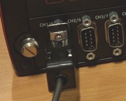
Most equipment to interface to CAN comes with a 9-pin D-sub plug (the male 9-pin D-sub connector with the pins). Having a plug on the CAN device is opposite to RS232 serial interfaces which often comes with a socket on the equipment. Here is a close up of some equipment with CAN interfaces provided using 9-pin D-sub plugs:
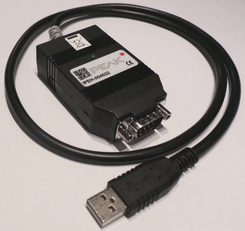
Here is another CAN interface device called PCAN-USB FD. This CAN to USB device is provided by PEAK-System Technik GmbH and supports standard CAN, extended CAN and CAN FD and uses a DB9 plug:
The 9-pin D-sub CAN bus cable pinout is defined by CANopn in the CiA 303-1 specification, shown in this table.
CAN Bus 9-pin D-Sub (DB9) Pinout Table
| Pin | Description |
|---|---|
| 1 | Reserved |
| 2 | CAN_L bus line dominant low (a.k.a. CAN low or CAN-) |
| 3 | Optional CAN ground |
| 4 | Reserved |
| 5 | Optional CAN shield |
| 6 | Optional ground |
| 7 | CAN_H bus line dominant high (a.k.a. CAN high or CAN+) |
| 8 | Reserved |
| 9 | CAN_V+, optional CAN external positive supply |
For basic CAN networking, this simplifies to:
| Pin | Description |
|---|---|
| 2 | CAN_L bus line dominant low (a.k.a. CAN low or CAN-) |
| 7 | CAN_H bus line dominant high (a.k.a. CAN high or CAN+) |
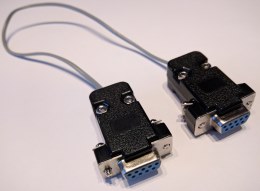
Therefore, for devices following the CANopen specification, the basic CAN bus cable is a length of single twisted pair cable with DB9 sockets (the female 9-pin D-sub connectors with the holes):
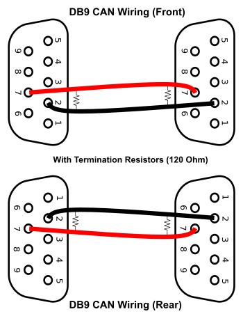
The simplest wiring is for pins 2 and 7 on the DB9 connectors to connect straight through. Remember that the pinout numbering changes when viewing the connector from the front, or the rear. The rear view will be used when constructing cables, and the front view when probing for signals:
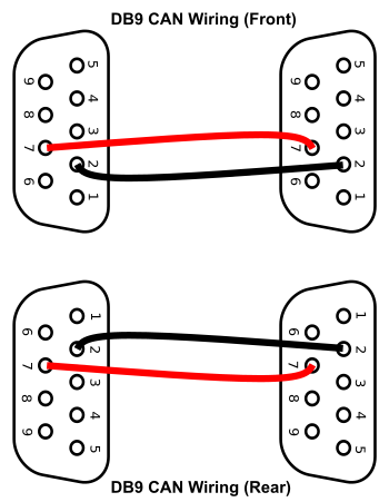
For a more resilient network, the CAN ground signals can be connected. When CAN ground is used and one of the CAN high or CAN low wires is damaged the network may still function. See the specifications for use of CAN ground lines.
CAN Bus Wiring Termination
The diagram at the start of the article was derived from a Wikimedia Commons CAN bus image. It shows a CAN bus schematic. At each end of the bus is a resistor. The CAN bus needs to have a termination resistor at each end. The termination resistor has a value of around 120 ohms. The resistor absorbs the CAN signal energy so that it is not reflected from the end of the cables back along the network to cause interference. When using DB9 plug and socket cabling it is possible to source a DB9 adapter with a 120 ohm resistor built-in:
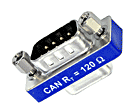
This 120 ohM CAN termination device plugs into the last device on the CAN network, the CAN DB9 cable then plugs into the DB9 terminator.
Many devices will have built-in support for CAN termination. Though this may mean that the device has to be opened to enable the internal CAN termination. The CAN termination within devices may be supported by a jumper link, a switch, solder pads or configured via software (see the manufacturers instructions).
When constructing cables the 120 ohm termination resistors may be soldered to the back of the DB9 connectors. This diagram illustrates the idea:
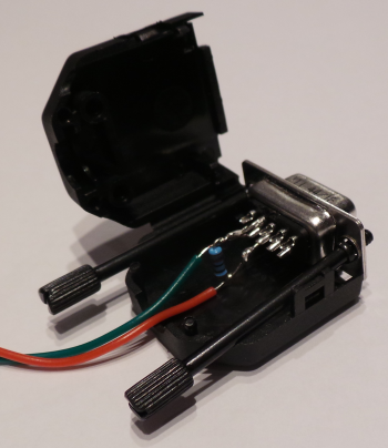
Here is an example of a 120 ohm termination resistor soldered onto the DB9 connector with the CAN wiring, located in the DB9 shell housing.
When bench testing short networks only one termination resistor may be sufficient. However, for best performance, the CAN bus should be terminated at both ends, especially for the higher bit rates.
The 120 ohm termination can be improved for further noise immunity, see the technical specifications for split termination information (using two 60 ohm resistors and a coupling capacitor connected between them and to ground, e.g. 4.7nF for 1 Mbps).
Networking Multiple Devices
Refer to the specifications for the limits on cable lengths for stub connections to the CAN bus. The CAN bus is a masterless multidrop network, therefore all CAN nodes simply attach to the CAN high and CAN low wires:
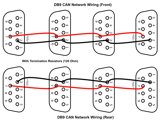
For bench testing this can be done using custom made cables, daisy-chaining DB9 straight-through splitter cables, or using ribbon cables fitted with 9-pin D-Sub Insulation Displacement Connectors (IDC).

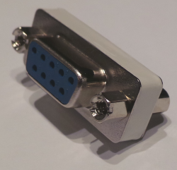
If the wrong plug or socket is on the end of a cable a DB9 gender changer can be used to convert it to the correct connection. They are available to convert plugs (males) to sockets (females), and sockets to plugs. They are useful for connecting two CAN devices for performing a loop test (sending a message out of the computer on one device and receiving it back on another device):
Automotive CAN Bus Cable
The CAN bus is common in cars. How do I know if my car has CAN-bus? The CAN bus is present in nearly all vehicles being made because of the requirement for authorities to access engine emissions (exhaust pollution) data from the engine management systems. The emissions data is read via the CAN bus. This requirement came into force in America from the late 1990s, in Europe and Japan from the early 2000s, and Australia from late 2000s. Cars are made for a global market, therefore all vehicles tend to have a CAN bus. The CAN bus is accessed via the OBD port:
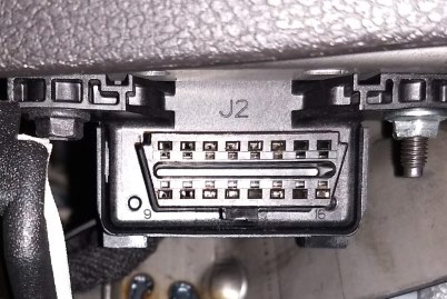
ODB Pin Usage
| Pin | Description |
|---|---|
| 1 | Manufacturer defined, e.g. VW/Audi/BMW ign. on, low speed GMLAN |
| 2 | SAE J1850 PWM Bus+ |
| 3 | Manufacturer defined, e.g. Ford medium or high speed CAN- (low), Chrysler CCD bus+ |
| 4 | Chassis Ground |
| 5 | Signal Ground |
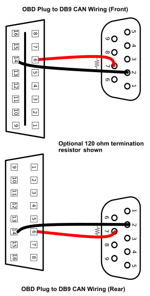
| 6 | CAN+ (high), ISO 15765-4, SAE J2284 |
| 7 | K-Line (ISO 9141-2, ISO 14230-4) |
| 8 | Manufacturer defined, e.g. BMW second K-Line |
| 9 | Manufacturer defined, e.g. BMW engine RPM |
| 10 | SAE J1850 PWM Bus- |
| 11 | Manufacturer defined, e.g. Ford medium or high speed CAN+ (high), Chrysler CCD bus- |
| 12 | Manufacturer defined |
| 13 | Manufacturer defined, e.g Ford PCM programming |
| 14 | CAN- (low), ISO 15765-4, SAE J2284 |
| 15 | L-Line (ISO 9141-2, ISO 14230-4) |
| 16 | Vehicle Battery +ve (live 12v or 24v) |
CAN Wiring ODB to DB9
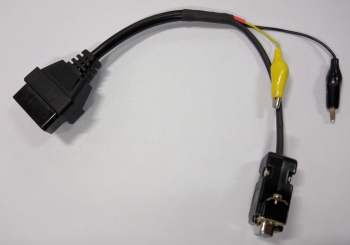
When wiring the OBD port to a CAN DB9 device a cable can be purchased or made. To make a cable an OBD plug (male) and a 9-pin D-sub socket (female) is required. When purchasing the OBD to CAN cable ensure that that DB9 socket matches the plug for the CAN device. Some OBD to DB9 cables do not conform to the CANopen standard (i.e. pins 2 and 7 on the DB9 connector). Also, be aware that the OBD socket on the vehicle exposes the cars 12-volt electrical system. This means the power pins on the OBD socket could have a voltage range from 10 volts to 18 volts (higher on trucks) and supply a dangerously high current. Therefore, precautions against electrical shock must be taken.
CAN Bus Arduino Interfaces
To build a sensor network, interface to a CAN bus, or view the CAN signals from vehicles there are lots of projects available on the Internet. Many microcontrollers have support for the CAN protocol. They are interfaced to CAN using a CAN transceiver chip. Many popular Single Board Computers (SBC) such as Arduino, Raspberry Pi and Texas Instruments Launchpad can interface to CAN via add-ons. Arduino CAN interfaces are popular, examples include the Seeed Studio CAN-BUS Shield and the SparkFun CAN-BUS Shield, and various compatibles. For a single board Arduino solution the Leonardo CAN BUS board used to be available.
Note: Some add-on boards with a DB9 plug need correctly configuring for CANopen compatibility (pins 2 and 7 on the DB9 socket).
CAN Bus Testing Equipment
Whilst Arduino interfaces provide a reliable method of connecting to and building a CAN bus sometimes professionally supported equipment is required. Especially if no CAN data packets should be dropped when debugging a system. Leading manufactures of CAN test equipment include:
See Also
- CAN-BUS Shield V2 for Arduino, by Seeed Studio
- What is an ECU?
- CAN Bus Loopback Test with PCAN USB Interfaces
- CAN Bus Explained - A Simple Intro by CSS Electronics
- CAN FD Explained - A Simple Intro also by CSS Electronics
- For a full list of all the articles in Tek Eye see the full site alphabetical Index.
Comments
On 17th August 2020 - Tc asked: What is the Maximum length, or Minimum, each Node can be on the Bus?
Tek Eye - The maximum cable lengths between the two end nodes on a CAN bus is dependant upon the bus data speed (i.e. the bit rate) in use. The bits per second (bps) signalling rate determines the maximum length of a cable run for a CAN bus. A low CAN bus data rate, for example 10 Kbps, will allow the bus to operate at a long distance of 6700 metres between the two ends of the bus. As the data rate increases the maximum bus length drops rapidly. At common vehicle CAN bus data rates the maximum bus lengths are:
- 125 Kbps - 530 metres
- 500 Kbps - 130 metres
- 1000 Kbps (1 Mbps) - 49 metres
Stub lengths should be kept short, 30cm for a 1 Mbps CAN bus, i.e. run the CAN bus cabling to each node rather than have long lengths of cabling for nodes on stubs.
On 15th September 2020 - andreaspenda92 asked: Hi, do you give online classes on CAN bus?
Tek Eye - Hello, online CAN bus classes are not provided at this time. Search for "can bus" on YouTube to see some resources.
On 30 November 2021 - Albert Fong asked: I will be installing an aftermarket stereo head unit (generic) into my W203 Mercedes C class. I also have an aftermarket Canbus Box with 16 pins or wires coming out of it. Is it possible to connect this box up so I can retain my steering wheel controls?
Tek Eye - Hi Albert, you need to look at the technical manuals for the head unit and CAN bus box. Some aftermarket head units that are specifically designed for a W203 will retain the steering wheel controls as they will correctly decode the signals. Some generic head units will have menu entries to allow functions specific to different cars models to be enabled (assuming the correct cable adapter, a.k.a. pigtail, has been used). A CAN bus box can change the signals between a head unit and the car to allow them to work together. This requires a CAN box for a specific car model, or a CAN box that can be programmed from a computer. The head unit and CAN bus box manufacturers should provide support.
Author:Daniel S. Fowler Published: Updated:
Comments
Post a Comment